- ...
- 3D SYSTEMS
- A&N Welding
- AA - Geen merkpagina
- ABA
- ABA Z&B
- Abb
- Abene
- ABUS
- Accut
- Accuway
- Aceti
- ADIGE
- Adira
- AFE
- AFM
- AGEO
- Agie
- Agiecharnilles
- AI HEMBRUG
- AIRHOUSE
- AKBEND
- Akira seiki
- AKYAPAK
- Alfra
- ALLMATIC
- Almi
- Alpha
- ALZMETALL
- AMADA
- Amc
- AMF Spanntechnik
- Amob
- ANAYAK
- ANDRITZ KAISER
- Angst
- Apec
- APOLLO
- ar iitalia
- ar italia
- Arcall
- ARD ART EDM
- Aris
- ARISTO
- Aritala
- ARKU
- ARKUS
- ARMSTRONG-BLUM
- Arntz
- ART Welding
- Arthur Klink
- ASQUITH
- Asquith butler
- Atkin
- Atlantic
- ATLAS
- Atomat
- Atron Germany
- Auerbach
- Auto well
- AVIA
- AVM
- AVM Angelini
- AWEA
- AXA
- AXZION
- BAD DUEBEN
- BAILEIGH
- BAKKER
- Barcorp
- Barnersdrill
- BAUER
- BAYKAL
- BEHRINGER
- Beka mak
- BEKAMAK
- BEND MOVE
- Bendmak
- Benzinger
- BERTHIEZ
- Beuter
- BEUTLER
- BEWO
- BEYELER
- Beyeler Mammut
- BIAX
- Biegenmaster
- Bieri AG
- Biglia
- BIGSTONE AUTOMATIC
- BIHLER
- BIKO
- Bilher
- BIMAK
- BINAR Sweden
- BIRLIK
- BISON Poland
- BLANSKO
- BLOHM
- BLUM
- BODE
- BOEHRINGER
- BOLDRINI
- BOLESTA
- Bolla
- Bollhof
- Bomar
- Boneham UK
- Bosch
- BOSCHERT
- BOST
- BOTT
- BPR
- Breda
- Breton
- Breuning
- BRIDGEPORT
- Brigeport
- BRISTOL
- Broadbent
- Brother
- BRUCKNER
- BuBend
- Buck
- Bucut
- BUISCAR
- Bullard
- Butler
- BWF
- BYSTRONIC
- C.P.S
- CABE
- Camu
- Cansa
- CARIF
- Carnaghi
- Casanova
- CAZENEUVE
- CBT
- CDMeccanica
- CEA
- Cematek
- CERATIZIT
- CERAZIZIT
- CETOS
- CEVISA
- CHARMILLES
- Cheto
- CHEVALIER
- Chinchmill
- CHIRON
- CIDAN
- Cinch mill
- Cinch-Mill
- CINCINNATI
- CIZETA
- CJM
- CKD
- CKD Blansko
- CLOOS
- CM Modena
- CME
- CMT
- Codatto
- COLCHESTER
- COLGAR
- COLLET
- COLLY BOMBLED
- COLOMBO & LENNA
- COMAC
- COMAL
- CombiPack
- COMESSA
- Comev
- CompAir
- Copren
- Cordia
- Cormac
- Cormak
- CORREA
- Correa Anayak
- Cosen
- Costa
- Cotek
- Crippa
- Crono
- CS Skates
- Csepel
- CT
- CTMS
- Cugir
- CUOGHI
- Cuteral
- Cybelec
- CyTec
- D'ANDREA
- DAEWOO
- DAEWOO DOOSAN
- Dahlih
- DAHLIH DCM
- Dainichi
- Daiss Partner
- Dalcos
- DANGO & DIENENTHAL
- Danieli
- DANOBAT
- DARLEY
- DATON
- Datron
- DAVI
- Davi Promau
- Deckel
- DECKEL MAHO
- Dees hydraulic
- DEGEN
- Delem
- Delken
- Delta
- DEMAG
- DEMMELER
- DEMOOR
- Dener
- DEPO
- DERATECH
- Desktop Metal
- Dimeco
- DIRINLER
- DMF
- DMG Gildemeister
- DMG MORI
- DMNC
- DMNC EDM
- DMT KERN
- DMTG
- DNR
- Doall
- Doganer makina
- Dominus
- DONAU
- DOOSAN
- DORMAC
- DORMAC DORIA
- DORRIES.
- DREISTERN
- DROOP & REIN
- DS Dorries Scharmann
- DS-Lifting
- DSK
- DTS
- DUGARD
- Dumeta
- DUNKES
- DUPLOMATIC
- DURMA
- Durmazlar
- DYNOBEND
- Dörries
- EBU
- ECKOLD
- ECOCA
- EDMO
- Edwards
- EIMELDINGEN
- Eisele
- Ekicontrol
- ELB
- ELB Schliff
- ELBO Controlli
- ELCORO
- ELIOG
- Elma
- ELMASS
- Elmatech
- Elsa
- ELUMATEC
- EMCO
- EMCO Famup
- EMP
- emsa
- Emsil
- ENERPAC
- Enshu
- EOS
- ERCOLINA
- ERGOMAN
- Erlo
- ERMAK
- ERMAKSAN
- ESAB
- Escomatic
- Esma
- ESS
- EST TICINO
- EUROMAC
- EUROMILL
- Everising
- Evisa
- Ewag
- EWM
- EWS
- EWU
- Exner
- FACCIN
- Fadal
- Fagima
- Fagor
- Faib
- FAMUP
- FANUC
- FARO
- Farrel
- FARROS
- FASTI
- FAT
- Fat (haco)
- Fat Wroclaw
- FAVRETTO
- Feeler
- Fehlman
- FEHLMANN
- Femco
- Ferex
- Fermat
- Fexac
- Fibro max
- FIL
- Fill
- Fim
- FINN POWER
- Finn-power
- FINNPOWER
- First
- Fischer
- Fives
- Flott
- FLOW
- FMB
- FMT
- FOERSTER
- Fokker Eckold
- Fonderia
- Foradia
- FOREST LINE
- FORKARDT
- Format
- Fornax
- FORTE
- FORTUNA
- FPS (DECKEL)
- FPT
- FptNews
- Fremtas
- Friggi
- FROEMAG
- Fromag
- FRONIUS
- FRORIEP
- Fulltontech
- Fumagalli Italia
- G. BREDA
- G.a.d.e
- G.B.C
- GabellaMacchine
- Gade
- Galileo
- GANRO Taiwan
- Garant
- GASPARINI
- GDW
- Gehring
- Geibel & Hotz
- GEKA
- Gelber-bieger
- GelberBieger
- Geldmacher
- GEMINIS
- Geminis Goratu
- Georg
- GEORGE KENDRICK
- Ger
- Gerardi
- GF Georg Fischer
- Giana
- Giddings&Lewi
- Giddings&Lewis
- GIETART
- GILDEMEISTER
- Gioria
- Giuseppe Giana
- Givi misure
- GksPerfekt
- Gleason
- GOCKEL
- GOLDEN SUN
- Gom
- GomMubea
- Goodway
- Govama
- Gpm titan
- GRAAF
- Graebener
- Graebner
- GRAFFENSTADEN
- GRESSEL
- Grindex
- Grit FEIN
- Grob
- Gs- hydro
- Gualdoni
- GUHRING
- Guifil
- Gurutzpe
- Gwf Mengele
- Gökcüoglu
- Haane
- Haas
- Habrama
- HACO
- HAEUSLER
- HAHN & KOLB
- HAIMER
- Handtmann
- Hankook
- Hannsa
- HAPREMEC
- Hardford
- Hardinge
- Hardinge Bridgeport
- Hare
- Harrison
- Hartford
- HAULICK ROOS
- Hawemat
- HBS Germany
- HDM
- Heatmasters OY
- Hebö
- Hedelius
- Hegenscheidt MFD
- Heidenhain
- Heinemann
- Heinrichsgluck
- HEINRICHSGLUECK
- Heller
- Hemburg
- Hemsaw
- HENNIGER --
- Henninger
- HERA
- Heraeus
- Herkules
- HERKULES WETZLAR
- HERMINGHAUSEN
- HERMLE
- Hestego
- HEXAGON
- HEYLIGENSTAEDT
- HGG
- Hifra
- HILMA
- HM
- HMC 500
- HNK
- Hochstrate
- HOEFLER
- HOESCH MFD
- Hofman
- Hofmann
- Hol-monta
- Holzmann
- Honor
- Hpm
- HSK
- Htt
- HUGH SMITH
- HURCO
- Hurco autobend
- HURON
- HWACHEON
- Hyd-mech
- Hyllus
- HYMO
- Hypertherm
- HYUNDAI
- HYUNDAI WIA
- HYWO
- Hänel
- Höfler
- I.m.a.l
- Ibarmia
- Iepco
- IGM
- IMAL
- IMATEC
- IMCAR
- IMET
- Ims
- Imsa
- INAXES
- INDUCTAFLEX
- Indumasch
- INNOCENTI
- Innse berard
- Innse berardi
- INNSE INNOCENTI
- INSITAN
- Intos
- INVERTER
- IRLE
- Isitan
- IXION
- JAEGER
- Jaespa
- Jafo
- Jagura
- Jakobsen
- Jammes
- Jap
- JBS
- Jenix
- JESSEY
- JET
- Jfmi
- Joen
- Johannsen
- Johansson
- Johnford
- JOHNFORDS
- JONES & SHIPMAN
- Jones- shipman
- JORNS
- Jorns ag
- Jouanel
- Juaristi
- JUNG
- JUNGENTHAL
- Junker
- Jutec
- Jörg
- Kaercher
- Kaeser
- KAISER
- KALTENBACH
- Kami
- KAMPA
- KAO FONG
- KAO MING
- Karl Deutsch
- KASTO
- Kasuga
- KAWASAKI
- Kawasaki robot
- Kef
- Kehren
- Keilinghaus
- Kekeisen
- KELLENBERGER
- KEMPPI
- Kent
- Keppler
- Kern
- Ki-Heung
- KIA Hyundai
- KIESERLING
- KiHEUNG
- Kimla
- King Rich
- Kingred
- KingRich
- KINGSLAND
- kipper trailer
- KIRA
- KISTLER
- KITAGAWA
- Kitchen walker
- KJELBERG
- Kjellberg
- Klaeger
- Klein
- Klemach
- Klingelnberg
- KNUTH
- Kohler
- KOIKE
- KOIKE ARONSON
- KOLB
- Koltech
- KONE
- KONECRANES
- KOVACO
- KOVOSVIT MAS
- Kramer
- Krewema
- Kromas
- KTS
- Kuhlmann
- Kuka
- KUMLA
- KUNZMANN
- Kurth+heuser
- L&W Machine Tools
- Lagun
- Lagun Goratu
- LAIP
- Lambert
- LAMBERT JOUTY
- LAMBERTINI
- Lang
- Lapmaster
- Lappmaster
- Lara
- Lauffer
- Lazzati
- Leadwell
- Legnani
- LEHMANN
- LEIFELD
- Leinen Swiss
- Leistitz
- Leistritz
- Leopoldo Pontiggia
- LGB
- LGB France
- LGM
- Licon
- Liebherr
- LIFT SIGMA
- LINCOLN
- LINDE
- LISSE
- Lissmac
- Loch
- Lockformer
- Loeser
- LORENZ
- Lovent
- LSK
- LTF
- LUCAS
- Lugong
- Lunan
- LUTZ
- LVD
- LVD STRIPPIT
- M&M
- M+A Maschinen
- M4M
- MAAG
- Machstroy
- MACMON
- MACO
- MACR
- Macri
- Macsoft
- MAEGERLE
- MAFI
- Magido
- MAHO
- MAHO GRAZIANO
- Make
- MAKEY BOWLEY
- Makino
- MANDELLI
- MAQFORT
- Marcovil
- MarioRiboldi
- MAS
- MAS Kovosvit
- Masima
- MATEC
- MATRA
- Matsuura
- Mavijet
- maxi horse trailer
- Maximart
- MAXION IXION
- MAZAK
- MazakVariaxis
- Mcm
- MEBA
- Meccanodora
- MECOF
- Memoli
- MEP
- Mepp
- Merli
- MESSER GRIESHEIM
- Metra
- MEWAG
- Mexpol
- MFD
- Mfl
- MG
- MGM
- MHG
- MIBA
- Micro abrasives
- MICROCUT
- Microcut Challenger
- Micromat
- Micromill
- Microstep
- Migatronic
- MIKRON
- Mikrosa
- Miller
- Millutensil
- MININI
- Mios
- Mirfos
- MITSUBISHI
- Mitutoyo
- Miyano
- MODUL
- Modulift
- MOHR
- Mollart
- Monforts
- MORI SEIKI
- MOSSNER
- MTE
- Mtm
- MUBEA
- Muller BEM
- Muller Opladen
- Munk & Schmitz
- Muratec
- Mvd
- Myford
- Nagel
- NAKAMURA
- Namsung
- Narvik
- NAVICOR
- NAXOS UNION
- Nicolas Correa
- Nigata
- NIKI AG
- Nikken
- Niles-Simmons
- NISSAN
- Nissin
- NKO
- NKOmachines
- NOBLE & LUND
- Nobs
- NORMFINISH
- Nosstec
- Nova
- NOVISA
- Nukon
- Oemb
- OERLIKON AIR LIQUIDE
- OKAMOTO
- OKK
- Okuma
- Omag
- Omca
- Omcca
- OMERA
- Omes
- OML
- OPTIMUM
- ORT Italia
- Otc
- PADOVANI
- PAMA
- Paragon
- PARAT
- Parkson
- Parmigiani
- PBR
- PBR Legnano
- PBT
- PBT Indumasch
- PBT Walba
- PDG
- PEBA
- PEDDINGHAUS
- Pedrazzol
- Pedrazzoli
- PEE-WEE
- PEGARD
- Pegas
- Pehaka
- Pehu
- PEI-POINT
- Peiseler
- PEMA
- PEMAMEK
- Perfect
- Perndorfer
- PERNO SNC
- PETEWE
- Pfauter
- Pfeifer
- PICOT
- PIESOK
- Pietro Carnaghi
- PILOUS
- Pilous TMJ
- PINACHO
- PINNACLE
- Pittler
- Pivatic
- PLANK
- PLANOLITH
- PLEIGER
- PLYMOVENT
- POINTER
- POLYMAT
- POREBA
- POSCH AUSTRIA
- POTISJE
- Pratt & Burnerd
- PRATT BURNED
- PREMATEX
- Presse ROSS
- PresseRoss
- Prima
- Prima Power
- Prinzing
- Pro King
- Profiroll
- ProKing
- PROTH
- PROTON
- ProtoTRAK
- ProTurn
- PULLMAX
- PULLMAX KUMLA
- PUMA
- QUASER
- QuickTech
- R&D
- RABBA
- RAFAMET
- Rainer
- Rapid
- RAS
- RASKIN
- Raster
- Ravensburg
- Reckermann
- REFORM
- REFORM HEIDENHAIN
- Reiden
- Reiden Swiss
- REIS
- REISHAUER
- Rems
- RENISHAW
- Repar 2
- Retop
- Retos
- Retro AG
- Rettificatrici favretto
- Rettificatrici rosa ermando
- Richter Lunetten
- Ridgid
- Rivelica
- Robosoft
- Roccia
- Rofin
- ROHM
- Romi
- Rosa
- Rosa ermando
- Rosilio
- ROUNDO
- RSA
- RT WELDING
- RUCKLE
- RUEBENACH BONN BEUEL
- RUHRMANN PRESSEN
- Ryazan
- RÖSLER
- Rüsch
- Saacke
- SABI
- Sachman
- Sachmann
- SACHMANN RAMBAUDI
- Sack Kiesselbach
- Sacma
- SAF
- SAF Airliquide
- SAF Curvatrici
- SAF Kjellberg
- SAF Tauring
- SAFAN
- SAFAN DARLEY
- SAFOP
- SAHINLER
- SAHM SPLICE
- Salvagnini
- Samag
- SAMCHULLY
- SANDVIK COROMANT
- SANGIACOMO
- SanRocco
- Saro
- SARTORE
- SASS TORINO
- Sasta
- Sato
- Sauter
- Saymak
- Scantool
- SCHAEFER
- SCHAERER - FACING
- SCHARMANN
- SCHAUBLIN
- Schaudt
- Schechtl
- Scherer
- SCHIESS
- SCHIESS FRORIEP
- Schlebach
- Schleiffstein
- SCHLEIFSTEIN
- Schmaltz
- SCHNEEBERGER
- Schnutz
- SCHRODER FASTI
- SCHROEDER
- Schröder
- SCHUBERT
- SCHUNK
- Schwarze
- Schwarze Robitec
- Schwarze Wirtz
- Schwarze-Robitec
- SciTeex
- Scudding
- SDT
- Sedin
- Seiger
- SENY
- SEPI SOUDAGE
- SEPO
- Sergi
- Seroma
- SERRMAC
- Sertom
- SHUIPO
- Shuztung
- Shw
- Sicmi
- Siemens
- Siemens toolcabinet
- Simasv
- SIMAVS
- SIMEK
- Simerom
- SKODA
- Skymaster
- Smd
- Smec
- SMEC SAMSUNG
- SMT Schleifstein
- Smtcl
- Smv
- SMW AUTOBLOK
- Sng
- SNIJSTAAL
- SNK
- SOCAD
- Sodick
- Soenen
- Soitaab
- Somo
- Sony
- SORALUCE
- Spark
- SPINNER
- Spiro
- Spühl
- STAHLI
- STAKO
- STAMA
- STANKO
- Stankoimport
- STARTRITE
- Steiner
- STIERLI
- Stierli Bieger
- STILL
- Stilmec
- STOLLE
- STOLTING
- STOPA
- Storebro
- Stuckmann & Hillen
- STUDER
- STYLE
- Stöckel
- Stöling
- Suce
- SUHNER
- SunFirm
- SUNNEN
- Super KIA TURN
- Super plasma
- Supermax
- Suprema
- Swl
- T-DRILL
- T-SLOT
- Tacchella
- Tacchi
- TADU
- TAH
- TaianHualu
- TAILIFT
- Taipu
- Taisei
- Tajmac-Zps
- TAKANG
- TAKISAWA
- Taksan
- Takumi
- Talurit
- Tam
- Tauring
- Taurus
- Taurus Wotan
- Tbt
- TBT Tiefbohrtechnik
- Tci
- TCS
- TDG Spain
- TDG Solutions
- Teap
- TECHNICA
- TECHNOMAGNETE
- Tecnocut
- TecnoMagnet
- TECNOMAGNETE
- Tecnostamp
- Tecoi
- TEHAG
- Tenova
- TENSOL
- TENSOL OEMB
- TESA
- Thiel
- THIELER
- THOMAN
- Tibo
- Timac
- Timesavers
- TIRA
- TITAN
- Titanroman
- TMJ
- Tnw
- Tomac
- TONG-IL
- TONGTAI
- TOP-TURN Taiwan
- TOPPER
- Tornos
- TOS
- TOS Hostivar
- TOS Trencin
- TOS TRENS
- TOS VARNSDORF
- TOSHULIN
- TOSKAR
- TOYODA
- Toyota
- Tracto
- Tracto Technik
- TRAK
- Transfluid
- Transnorm System
- TRAUB
- TRENNJAEGER
- Trens
- Trepel
- Trevisan
- Triumph
- trolleys
- TroTec
- TRUMPF
- TRUMPF EHT
- TSCHUDIN
- TTS
- TUBOMAT
- TURNCRAFT
- Twin Seam
- UKB
- Umac
- Umaro
- Ungerer
- Uni-TECH
- UNION
- UNION HECKERT
- Unisig
- Unisign
- Urpe
- Ursus
- Ursviken
- Utas
- Uzay
- Uzma
- VacuLift
- Valdarno
- Variobend
- VDF
- VDF Boehringer
- VDF BOEHRINGER
- VDF Wohlenberg
- VEGO
- VERACHTERT
- VETTER
- VICTOR
- Victor Taichung
- VictorTaichung
- Vigel
- Viking
- Vimercati
- Vingriai
- VIPER
- VLM
- Voest Alpine
- VOESTALPINE
- VOGT Swiss
- VOLZ
- Voortman
- Wafios
- Wafois
- WAGNER
- Walba
- Waldrich
- Waldrich Coburg
- WALDRICH SIEGEN
- Walker Hagou
- WALTER
- Walter Eckold
- Walter Meier AG
- Warcom
- Waterjet
- Webster&bennet
- Webster&Bennett
- WECO
- Weeke
- Weidenmann
- WEILER
- WEILER MAS
- Weingärtner
- WEIPERT
- Weisser Heilbronn
- WELE
- Wema
- Wemas
- Wendt
- Wenzel
- Westekemper
- WF
- WFL
- WFL Austria
- Wila
- Wisconsin
- WJS
- WK IndustrieTechnik
- WMW
- WMW DESSAU
- WMW Heckert Meuselwitz
- WMW Meuselwitz
- WMW Zeulenroda
- WMZ
- WOHLENBERG
- Woochang
- Wortelboer
- WORTELBOER HOLLAND
- Wotan
- WOTAN SACEM
- Wuhan
- Wuxi Runyuan
- WZ
- XYZ Printing
- YAM
- YANG
- Yawei
- YC superjet
- YC Taichnung Taiwan
- YCM
- YCM Supermax
- Yoga
- YOU JI
- YOUji
- YSD
- YSP
- YU SHINE
- Zani
- ZAYER
- ZDAS
- Zdaz
- ZERBST
- Zeulenroda
- Ziersch
- Ziersch & Baltrusch
- Zimmerman
- Zmm
- ZMM Sliven
- Zocca
- Zoller
- ZOP BEND
- Zopf
- Zps
- Zymt
- Home
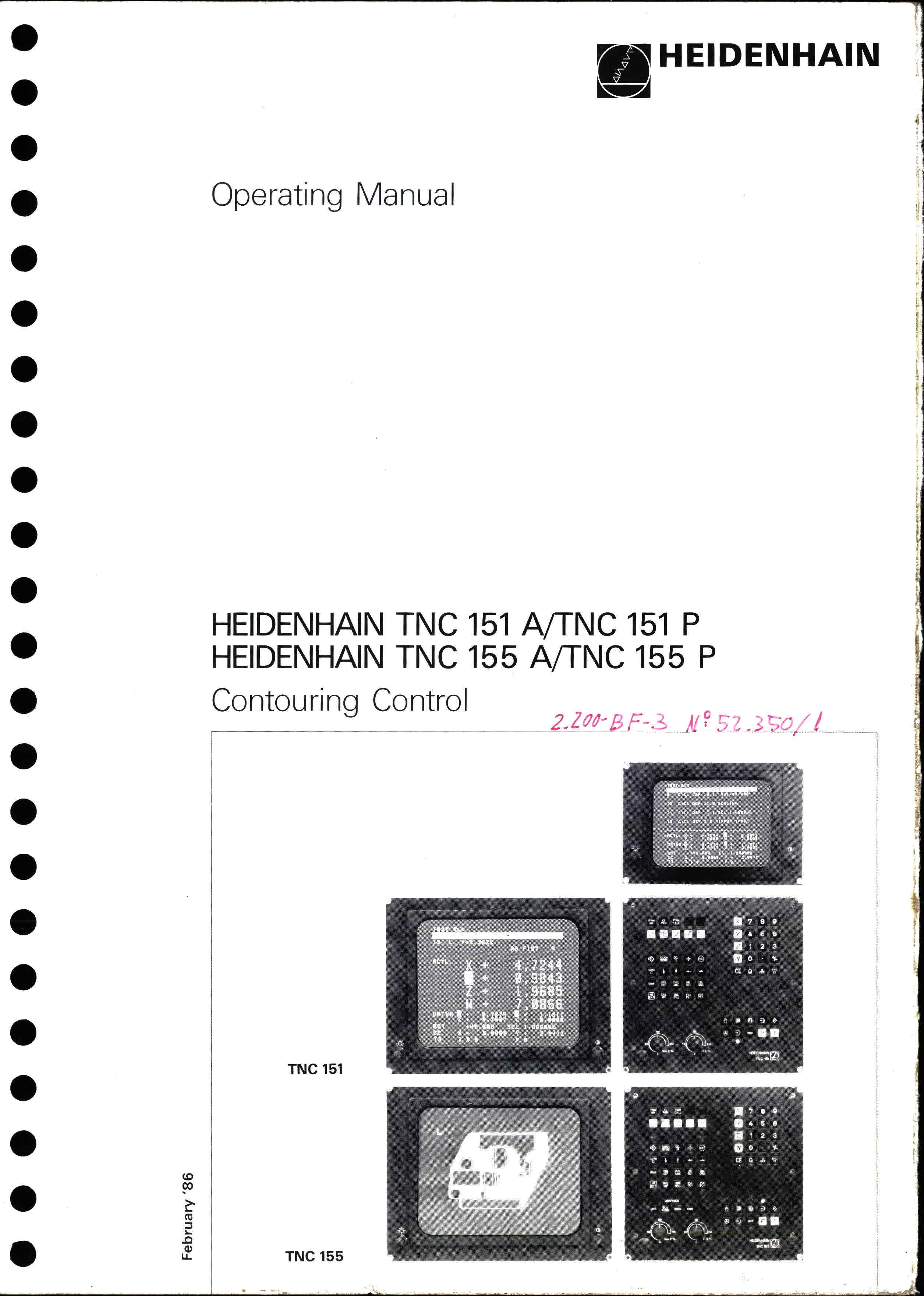
- Heidenhain Tnc 151, 155 contouring control
Heidenhain Tnc 151, 155 contouring control
The HEIDENHAIN TNC 151/TNC 155 is a contouring control system designed for 4 axes, with linear axes X, Y, and Z, and an optional axis 1V for connecting a rotary table or another linear axis. This control system enables various machining operations, including linear and circular interpolation, allowing for the machining of complex contours.
Here are some key features and capabilities of the TNC 151/TNC 155:
- Linear interpolation in any three axes and circular interpolation in two linear axes.
- Program entry can be done in HEIDENHAIN plain language dialogue or standard ISO 6983 (G-codes) format.
- Dialogues, entry values, machining programs, fault/error messages, and position data are displayed on the VDU-screen.
- The program memory can store up to 32 programs with a total of 3100 blocks.
- Machining programs can be entered manually or electronically via a data interface.
- External storage of programs is possible using HEIDENHAIN magnetic tape units (ME 101/ME 102).
- The control system performs program checks without machine movement in the "program test" mode and provides graphics simulation for program runs.
- Programs compiled on previous control models (TNC 145 and TNC 150) are fully compatible with the TNC 151/TNC 155.
- The buffer battery serves as the power source for the machine parameter store and program memory. If the battery needs replacement, an error message will be displayed.
Regarding coordinate systems and dimensioning, the control system allows for setting the workpiece datum by assigning numerical values (REF-values) to reference points. The control automatically memorizes these values, enabling easy reproduction of the workpiece datum after a power supply interruption.
Overall, the HEIDENHAIN TNC 151/TNC 155 offers advanced features for precise and efficient machining operations, with compatibility with previous control models and convenient workpiece datum setting capabilities.
Programming Introduction:
Just as with manually operated machine tools, programming is essential for NC-machine tools. The sequence of operations remains the same. While each working step on manually operated machines needs execution by the operator, an NC-machine relies on electronic control for calculating the tool path, coordinating feed movements of machine slides, and supervising spindle speed. The control receives information from a program entered into it.
Programming of Tool Compensation:
**Central Tool Store Activation:**
Starting from software version 03, TNC 151 and TNC 155 can activate a central tool store via machine parameters. The central tool store is addressed through program number 0 and can be amended, output, and input in the "programming" mode. It can store up to 99 tools, each with a tool number, length, radius, and store location.
**Toolchanger with Random Select Facility:**
When using a toolchanger with random select (variable tool location coding), the control is responsible for tool management. The random tool selection works by searching for the next tool while one is being used for machining. When a tool change occurs, the control exchanges the last used tool for the new one, registering its tool number and last placed store location. Tools that allocate three locations due to their size can be defined as special purpose tools, always located at a fixed location.
**Blockwise Transfer:**
In the "blockwise transfer" mode, compensation transfer values can be called up from the central tool store.
**Tool Call:**
With TOOL CALL, a new tool and its compensation values for length and radius are called up. Besides the tool number, the control needs to know which axis the spindle will operate in to apply both length and radius compensation correctly. After specifying the working spindle axis, the spindle speed must be entered. If the spindle speed is outside the permissible range, an error message "WRONG RPM" is displayed during program run.
**Tool Change Procedure:**
During a tool change, the control positions the tool to a position with non-compensated nominal values for execution. This is done via TOOL CALL 0. Traverses to the tool change position can be executed via auxiliary functions M91, M92, or via a PLC-positioning command. For manual tool changes, a STOP command is required before the TOOL CALL command. An automatic tool change doesn't need a programmed STOP, and program run continues when the change is finalized.
Programming of Workpiece Contours:
**Radius Compensation - Path Compensation:**
For automatic compensation of tool length and radius, as entered in the TOOL DEF block, the control needs to know if the tool is located to the right, left, or directly on the contour in the feed direction. If the tool is moving with path compensation, where the centerpoint of the tool moves with the programmed radius considered, it follows a path parallel to the workpiece contour offset by the tool radius.
**Feed Rate F/Auxiliary Functions M:**
The feed rate, i.e., tool path speed, is programmed in mm/min. or 0.1 inch/min. For rotary tables (A, B, or C-axis), the entry value is in °/min. The feed rate override on the control panel can vary from 0 to 150%. Max entry values (rapid) for the feed rate are 15999 mm/min. or 6299/10 inch/min. The max feed rate of individual machine axes is determined by machine parameters set by the machine tool builder. Auxiliary functions, denoted by the address letter M and a code number, control special machine functions and tool path behavior.
**Subprograms and Program Part Repeats:**
Labels with numbers can mark program sections as subprograms (sub-routines). Jumps can be made to such label numbers during program run. Labels are set by pressing the LBL key, and numbers from 0 to 254 may be allocated. Label number 0 signifies the end of a subprogram and acts as a return jump marker. Subprograms are retrieved via LBL CALL command and can be repeated with the REPEAT command.
**Parameters:**
Numerical values within a program can be substituted by variable parameters, denoted by the letter O and a number between 0 and 99. Parameters can be entered with a negative sign, and the correlation of values to parameters can be direct or via mathematical and logical functions.
**Canned Cycles:**
Peck Drilling involves multiple steps including setup clearance, total hole depth, pecking depth, dwell time, and feed rate. The tool makes repeated penetrations until the programmed hole depth is reached, retracting to the starting position between each penetration. At the end of the cycle and after the dwell time, the tool returns to the starting position. Arithmetical signs denote directions and distances.
**Canned Cycles:**
**Slot Milling:**
"Slot milling" is a combined rough/fine cut cycle where the slot is parallel to an axis of the current coordinate system, which may need rotation if required. It involves setup clearance, milling depth (depth of slot), pecking depth, feed rate for pecking, first side length (finished length of slot), and second side length (finished slot width). The rough cut cycle involves the tool penetrating the workpiece, milling the slot in the length direction, and repeating until the programmed milling depth is reached.
**Pocket Milling:**
The pocket milling cycle can be performed as a rough cut or fine cut cycle. The sides of the pocket are parallel to the axes of the current coordinate system, which may require rotation if necessary. It includes setup clearance, milling depth (depth of pocket), pecking depth, feed rate for pecking, first side length (length of pocket parallel to the first main axis), and second side length (width of pocket). The rotation determines the rotation direction of the cutter path.
**Mirror Image:**
Mirror imaging an axis at the zero datum changes the direction of the axis and reverses the arithmetic signs of all coordinates, resulting in a mirrored image of the programmed contour or hole pattern. It's only possible in the working plane, either by reversing one axis or both simultaneously. Machining mirror image in one axis reverses the machining direction, affecting the contour's original milling direction. Mirror imaging in two axes further reverses the machining direction, maintaining the contour's original direction.
**Zero Datum:**
When programming mirror imaging, the coordinate axis for mirror imaging should lie exactly between the mirrored contour and the contour to be mirrored. If necessary, a datum shift should be programmed before the cycle definition.
**Program Editing:**
**Deletion and Insertion of Blocks:**
Blocks within a program can be erased by pressing DEL. Block deletion is only possible in the edit mode. Single blocks should be deleted carefully to ensure only the current block is erased. New blocks can be inserted at any desired location within the program. If the storage capacity of the program memory is exceeded, an error message is displayed. This error also appears if attempting to insert a block subsequent to the END-block of the program.
**Program Run:**
**Re-entry After Termination:**
A program can be restarted after an interruption or termination, but certain provisions must be made to prevent workpiece damage:
- The tool must move to the position it was at before the interruption.
- The program must be restarted with the block in which the interruption took place.
- If the tool has been changed due to a tool break, the new tool data (tool definition) must be entered, and the tool is then re-called in the MD1-mode. The workpiece must then be touched again by the tool.
**Machine Parameters:**
To ensure that the machine can perform control commands correctly, the control must be aware of specific machine data such as traverses, accelerations, etc. These data are determined by the machine tool builder using machine parameters.
Machine parameters are entered during the initial commissioning procedure of the control, either via an external data carrier (e.g., ME-cassette with stored machine parameters) or by manual entry.
After a power interruption with either empty or missing buffer batteries, the machine parameters must be re-entered. In this case, they are requested by the control dialogue.
Certain machine parameters are accessible when using the MD1-mode, such as switching over from HEIDENHAIN plain language to the ISO-programming language.
The buffer batteries serve as the power source for the machine parameter memory and the program memory. They are located beneath the cover on the control panel.
If the message "EXCHANGE BUFFER BATTERY" is displayed, the batteries must be exchanged (they last for approximately 1 week after this message).
Battery exchange should be performed with the mains power switched on to supply power to the TNC-memories. If the batteries are exchanged with the power off, all memories are erased, and machine parameters must be reentered.